
Volts, Amps, Ohms and Watts: The Water Analogy, Done Properly
Volts, Amps, Ohms and Watts
Nobody fails at this trade because they could not recite Ohm's law. They fail because they never connected it to the thing in their hand — the crimp that got warm, the light that went dim at the far corner of the vehicle, the fuse that would not stop blowing.
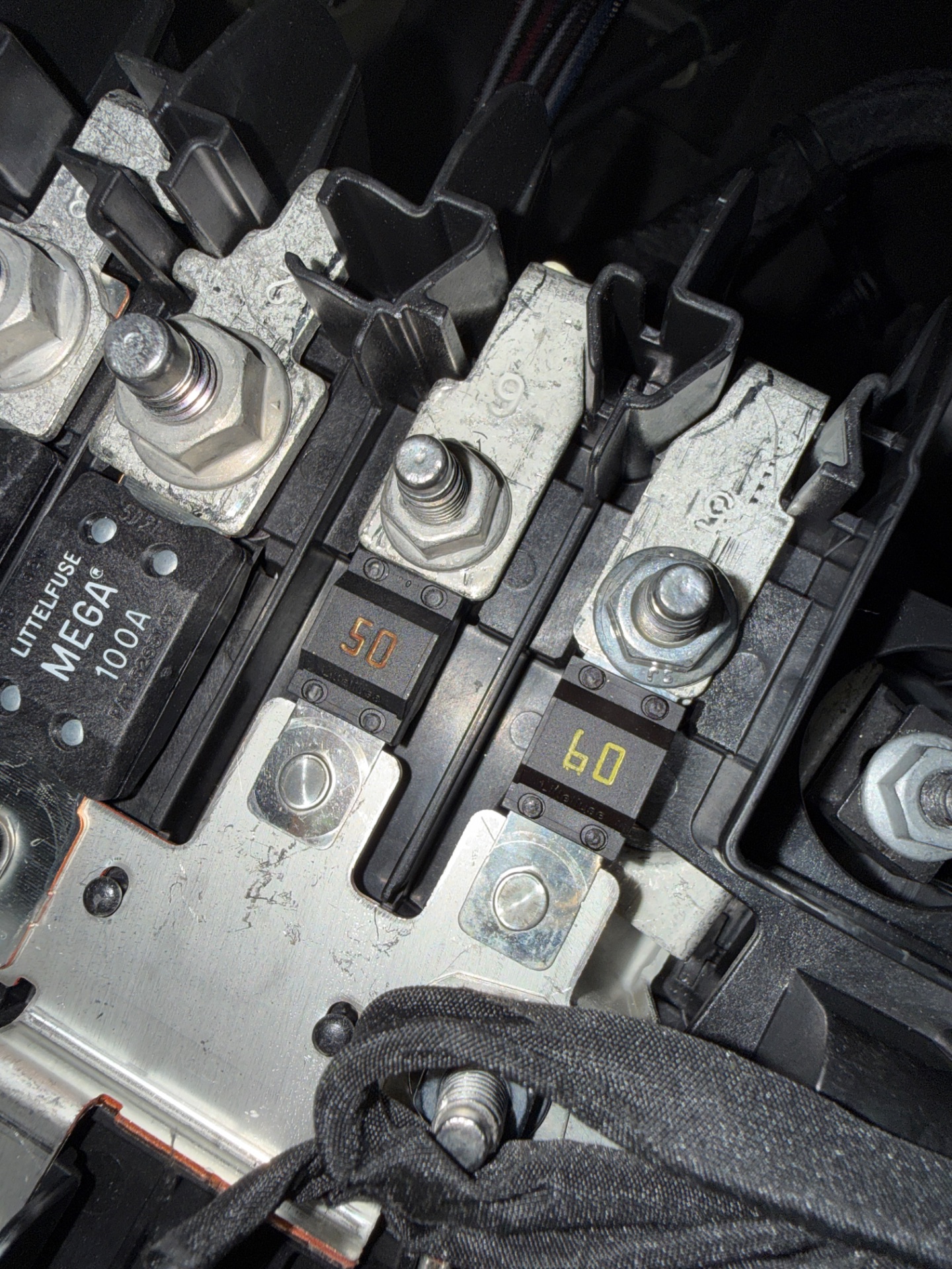
Four numbers, and the analogy Whelen uses
Whelen's own free installer course, INT 110 Basics of Electricity, opens with water in a pipe, and it opens there for a good reason: every quantity has a physical twin you can picture.
- Volts (V) — pressure
- How hard the system is pushing. A 12-volt system is a low-pressure system, which is why small resistances matter so much.
- Amps (I) — flow
- How much is actually moving. Amps size the wire, size the fuse, and start the fire.
- Ohms (Ω) — pipe size
- What resists the flow. Thin wire, a loose crimp, a painted ground, corrosion. Resistance is the enemy the whole lesson is about.
- Watts (W) — work done
- Volts × amps. The light, the siren and the heat in a bad joint are all watts.
The analogy is not decoration. It predicts behaviour. Raise the pressure and more flows. Narrow the pipe and less flows, and the narrow section gets hot. Every diagnosis you will ever do is one of those two sentences applied to a specific piece of copper.
The formula you will actually use
Ohm's law is V = I × R, and you will rearrange it three ways in a career. The one you will use every single day is the other one.
P = V × I
“The formula you'll use most.”
Whelen works the example as a 10-amp light at 12 volts: 120 watts. Run it the other way and it becomes the number you need at the quoting stage, when a spec sheet gives you watts and your load budget wants amps.
Think firstA Federal Signal Pathfinder PF200 siren amplifier is rated at 200 watts and its data sheet lists an operating current of 16 amps. Does that arithmetic work, and what does it tell you about the feed?tap to reveal
200 W ÷ 12.8 V = 15.6 A, so the published 16 A is exactly what the physics says, with nothing hidden. That is your check on any spec sheet: if watts ÷ volts does not land near the published amps, you are reading peak, average or output power, and you need to know which.
It also tells you this is a pulsed 16 A load, not a steady one. It hits that number on every tone peak, which is why an undersized siren feed shows up as a controller that resets rather than a siren that is merely quiet.
Working it on real equipment
Numbers from catalogues are abstract until you put them in a vehicle. Whelen publishes current draw per lighthead because installers need it for exactly this.
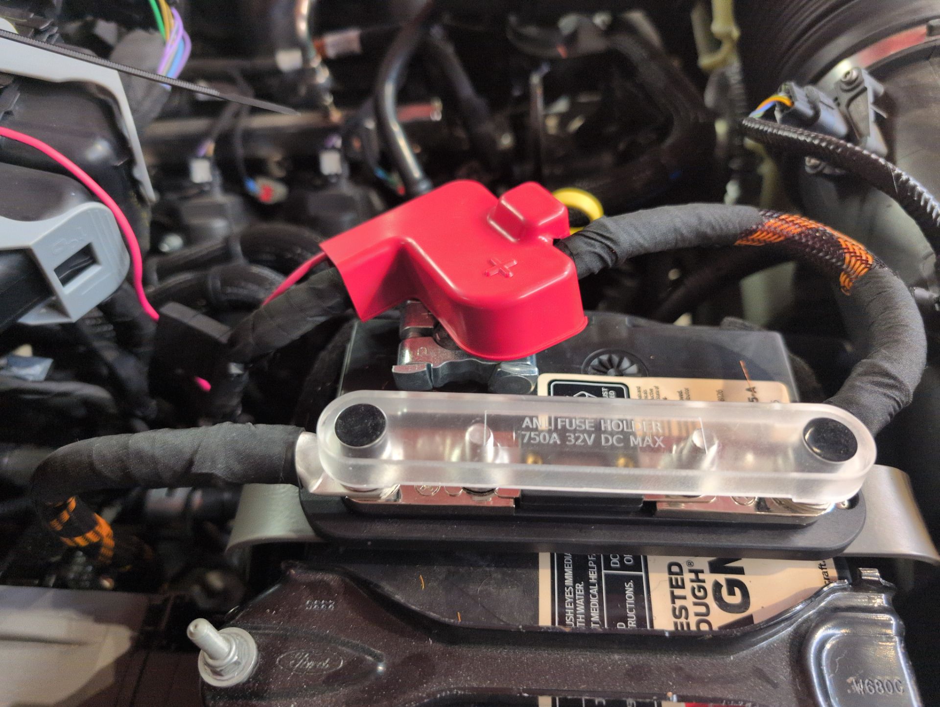
Current draw per device is the raw material for everything downstream: the fuse size, the wire gauge, the controller output you land it on, and whether the alternator can carry the build at idle. A technician who does not collect these numbers is guessing, and the guess is always optimistic.
Why voltage drop is not a voltage problem. It is a heat problem.
Whelen's course states it in one line: voltage drop is power dissipated as heat. That is worth sitting with, because it converts an invisible electrical quantity into a physical event with a location.
Think firstA 20-amp circuit runs through a crimp that was made with pliers. The joint has 0.1 ohm of resistance — a number a cheap meter can barely read. How much power is being dissipated inside that connector?tap to reveal
P = I² × R = 20 × 20 × 0.1 = 40 watts, inside a lump of metal the size of a pea. A 40 W soldering iron will melt solder. This one is wrapped in insulation, under a trim panel, with nobody watching.
The circuit still works. The light still lights. The only symptoms are a slightly dim head and a connector that smells faintly of hot plastic — until the day the insulation gives up.
This is why "it works" and "it is right" are different findings, and why voltage-drop testing beats continuity testing. A joint that is 0.1 Ω passes a continuity beep with flying colours. Under load it is a heater.
What the battery is telling you
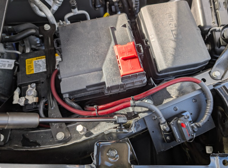
| Reading | Condition | What to do |
|---|---|---|
| 12.6 V or higher, engine off | Fully charged (AGM reads a touch higher) | Good. Now go find the second number |
| 12.4 V | About 75% charged | Charge it before you load-test anything |
| 12.2 V or lower | Half charged or failing | Charge, load-test, then suspect a parasitic draw |
| 13.5–14.7 V, engine running | Charging normally | Normal |
| Below 13.2 V with equipment on | Alternator cannot keep up, or a bad connection | Measure at the alternator, then walk the drops |
| 15.0 V or higher | Regulator fault | Stop. Electronics cook above about 16 V |
Every measurement you take later is compared against these two numbers. A build that behaves perfectly on a bench supply and badly in the vehicle is usually not a build problem at all; it is a 12.1 V battery that nobody checked before the diagnosis started.
Amps size the wire. The wire sizes the fuse.
Voltage gets the attention because it is the number on the badge. Current does the damage. The whole chain of decisions in the next three lessons runs in one direction, and it runs downhill from current.
- Find the device's worst-case continuous current from the spec sheet, not from a forum post.
- Add the run length, out and back, because copper resistance is per foot and the return leg counts.
- Choose a wire big enough to carry the current and hold the voltage drop inside target.
- Choose a fuse that opens before that wire is in trouble — never a fuse chosen to suit the device.
- Land it on a power source that is live when the equipment needs to be live.
Half of every circuit is the way back
New technicians chase positives. Circuits are loops: out through the fuse and the device, back through the ground. On a vehicle, that return is usually the body shell, which is a large piece of painted, bonded, corrodible steel.
Six chargers, one cigarette lighter
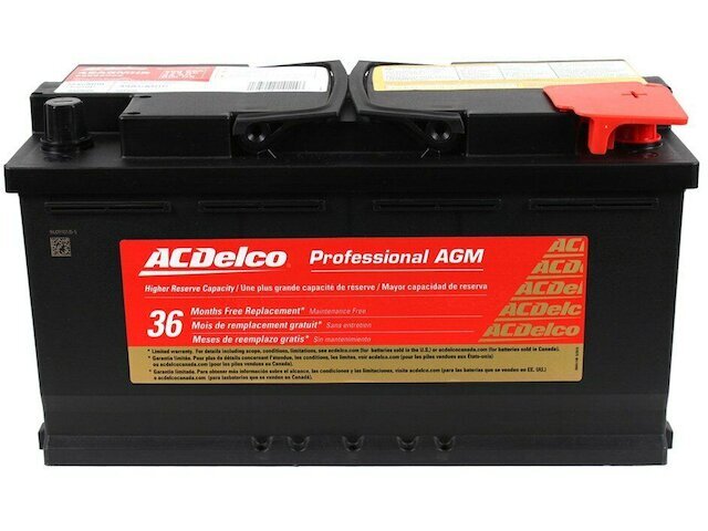
A fire chief posting in an upfitter screw-ups group found six box-light chargers daisy-chained through cigarette-plug splitters, one splitter spliced into another, on an install about twenty years old. Nothing had caught fire. Everything about it was arithmetic nobody had done: a circuit built for one accessory carrying six, with no added protection and no return path anyone had sized.
EVT Upfitter Hacks and Screw-Ups ↗Wattages add. Currents add. A circuit does not care that each item is small. The fuse behind it was chosen for the factory accessory, and the wire behind the fuse was chosen for the fuse.
The same four numbers, three jobs
🔧 If you turn the wrenches
Collect current draws before you cut wire. Measure the battery before you diagnose. When something is dim or weak, measure the drop under load instead of guessing which part is bad.
📋 If you run the fleet
Ask for the load calculation as a deliverable. A shop that can hand you a per-circuit current list has done the arithmetic; a shop that cannot has guessed, and guesses fail in year two.
⭐ If you sign the PO
You do not need the formula. You need to know it exists and that somebody used it. The question is "what is the total added load on this car, and what does the alternator make at idle?"
- What does each device actually draw, and is that continuous or peak?
- What is the resting and charging voltage on this vehicle, measured today?
- Where is the return path for this circuit, and what is it bolted to?
- If this circuit gets warm in service, what is the first thing I will suspect?
- Volts push, amps flow, ohms resist, watts do the work: V = I × R and P = V × I.
- Voltage drop is not lost voltage, it is heat at a specific place: P = I² × R.
- 12.6 V at rest, 13.5–14.7 V charging. Check both before diagnosing anything.
- Current sizes the wire; the wire sizes the fuse. Never the other way around.
- Half of every circuit is the return. Most "impossible" faults live there.
Volts, Amps, Ohms and Watts
Nobody fails at this trade because they could not recite Ohm's law. They fail because they never connected it to the thing in their hand — the crimp that got warm, the light that went dim at the far corner of the vehicle, the fuse that would not stop blowing.
Four numbers, and the analogy Whelen uses
Whelen's own free installer course, INT 110 Basics of Electricity, opens with water in a pipe, and it opens there for a good reason: every quantity has a physical twin you can picture.
- Volts (V) — pressure
- How hard the system is pushing. A 12-volt system is a low-pressure system, which is why small resistances matter so much.
- Amps (I) — flow
- How much is actually moving. Amps size the wire, size the fuse, and start the fire.
- Ohms (Ω) — pipe size
- What resists the flow. Thin wire, a loose crimp, a painted ground, corrosion. Resistance is the enemy the whole lesson is about.
- Watts (W) — work done
- Volts × amps. The light, the siren and the heat in a bad joint are all watts.
The analogy is not decoration. It predicts behaviour. Raise the pressure and more flows. Narrow the pipe and less flows, and the narrow section gets hot. Every diagnosis you will ever do is one of those two sentences applied to a specific piece of copper.
The formula you will actually use
Ohm's law is V = I × R, and you will rearrange it three ways in a career. The one you will use every single day is the other one.
P = V × I
“The formula you'll use most.”
Whelen works the example as a 10-amp light at 12 volts: 120 watts. Run it the other way and it becomes the number you need at the quoting stage, when a spec sheet gives you watts and your load budget wants amps.
Think firstA Federal Signal Pathfinder PF200 siren amplifier is rated at 200 watts and its data sheet lists an operating current of 16 amps. Does that arithmetic work, and what does it tell you about the feed?tap to reveal
200 W ÷ 12.8 V = 15.6 A, so the published 16 A is exactly what the physics says, with nothing hidden. That is your check on any spec sheet: if watts ÷ volts does not land near the published amps, you are reading peak, average or output power, and you need to know which.
It also tells you this is a pulsed 16 A load, not a steady one. It hits that number on every tone peak, which is why an undersized siren feed shows up as a controller that resets rather than a siren that is merely quiet.
Working it on real equipment
Numbers from catalogues are abstract until you put them in a vehicle. Whelen publishes current draw per lighthead because installers need it for exactly this.
Current draw per device is the raw material for everything downstream: the fuse size, the wire gauge, the controller output you land it on, and whether the alternator can carry the build at idle. A technician who does not collect these numbers is guessing, and the guess is always optimistic.
Why voltage drop is not a voltage problem. It is a heat problem.
Whelen's course states it in one line: voltage drop is power dissipated as heat. That is worth sitting with, because it converts an invisible electrical quantity into a physical event with a location.
Think firstA 20-amp circuit runs through a crimp that was made with pliers. The joint has 0.1 ohm of resistance — a number a cheap meter can barely read. How much power is being dissipated inside that connector?tap to reveal
P = I² × R = 20 × 20 × 0.1 = 40 watts, inside a lump of metal the size of a pea. A 40 W soldering iron will melt solder. This one is wrapped in insulation, under a trim panel, with nobody watching.
The circuit still works. The light still lights. The only symptoms are a slightly dim head and a connector that smells faintly of hot plastic — until the day the insulation gives up.
This is why "it works" and "it is right" are different findings, and why voltage-drop testing beats continuity testing. A joint that is 0.1 Ω passes a continuity beep with flying colours. Under load it is a heater.
What the battery is telling you
| Reading | Condition | What to do |
|---|---|---|
| 12.6 V or higher, engine off | Fully charged (AGM reads a touch higher) | Good. Now go find the second number |
| 12.4 V | About 75% charged | Charge it before you load-test anything |
| 12.2 V or lower | Half charged or failing | Charge, load-test, then suspect a parasitic draw |
| 13.5–14.7 V, engine running | Charging normally | Normal |
| Below 13.2 V with equipment on | Alternator cannot keep up, or a bad connection | Measure at the alternator, then walk the drops |
| 15.0 V or higher | Regulator fault | Stop. Electronics cook above about 16 V |
Every measurement you take later is compared against these two numbers. A build that behaves perfectly on a bench supply and badly in the vehicle is usually not a build problem at all; it is a 12.1 V battery that nobody checked before the diagnosis started.
Amps size the wire. The wire sizes the fuse.
Voltage gets the attention because it is the number on the badge. Current does the damage. The whole chain of decisions in the next three lessons runs in one direction, and it runs downhill from current.
- Find the device's worst-case continuous current from the spec sheet, not from a forum post.
- Add the run length, out and back, because copper resistance is per foot and the return leg counts.
- Choose a wire big enough to carry the current and hold the voltage drop inside target.
- Choose a fuse that opens before that wire is in trouble — never a fuse chosen to suit the device.
- Land it on a power source that is live when the equipment needs to be live.
Half of every circuit is the way back
New technicians chase positives. Circuits are loops: out through the fuse and the device, back through the ground. On a vehicle, that return is usually the body shell, which is a large piece of painted, bonded, corrodible steel.
Six chargers, one cigarette lighter
A fire chief posting in an upfitter screw-ups group found six box-light chargers daisy-chained through cigarette-plug splitters, one splitter spliced into another, on an install about twenty years old. Nothing had caught fire. Everything about it was arithmetic nobody had done: a circuit built for one accessory carrying six, with no added protection and no return path anyone had sized.
EVT Upfitter Hacks and Screw-Ups ↗Wattages add. Currents add. A circuit does not care that each item is small. The fuse behind it was chosen for the factory accessory, and the wire behind the fuse was chosen for the fuse.
The same four numbers, three jobs
🔧 If you turn the wrenches
Collect current draws before you cut wire. Measure the battery before you diagnose. When something is dim or weak, measure the drop under load instead of guessing which part is bad.
📋 If you run the fleet
Ask for the load calculation as a deliverable. A shop that can hand you a per-circuit current list has done the arithmetic; a shop that cannot has guessed, and guesses fail in year two.
⭐ If you sign the PO
You do not need the formula. You need to know it exists and that somebody used it. The question is "what is the total added load on this car, and what does the alternator make at idle?"
- What does each device actually draw, and is that continuous or peak?
- What is the resting and charging voltage on this vehicle, measured today?
- Where is the return path for this circuit, and what is it bolted to?
- If this circuit gets warm in service, what is the first thing I will suspect?
- Volts push, amps flow, ohms resist, watts do the work: V = I × R and P = V × I.
- Voltage drop is not lost voltage, it is heat at a specific place: P = I² × R.
- 12.6 V at rest, 13.5–14.7 V charging. Check both before diagnosing anything.
- Current sizes the wire; the wire sizes the fuse. Never the other way around.
- Half of every circuit is the return. Most "impossible" faults live there.
There are no comments for now.
to be the first to leave a comment.